

Corner balancing a automobile has been one among those things that seemed off-limits to the typical automotive DIY enthusiast.
You will discover a big selection of electronic scales from a speed shop like Summit Racing; nevertheless, a ‘decent’ set will set you back no less than $1,000, and a higher-quality set will cost double that.
You need to use the lavatory scale hack, where you jack the automobile up and lower it on a set of low cost bathroom scales. I even tried this back in 2020 with Project Rough, my ER34 Nissan Skyline GT-T, and had… moderate success.

To do that appropriately, you could ensure you’re working on a superbly flat surface. The automobile must be as level as possible while on the scales – i.e., on some form of platform – and you wish a approach to loosen up the arms after jacking the automobile up to maneuver the scales into position.

It’s quite the dance, and there are a bunch of variables where things can go fallacious. One among my scales broke resulting from going far beyond the utmost weight limit of 130kg (286lbs).

So, measuring the burden in any respect 4 corners, making any adjustments, and having to perform the entire circus again made this system removed from practical. It gave the look of dedicated electronic scales were still the one viable approach.
Or Is It…

Fast-forward a number of years, and I discovered a YouTube channel called SuperfastMatt. Matt’s videos are as humorous as they’re insightful, and one called I Invented a Higher Solution to Weigh Your Automotive. And it’s Cheaper, Too. discusses how you should utilize leverage and a little bit of math to calculate the burden at any given corner.

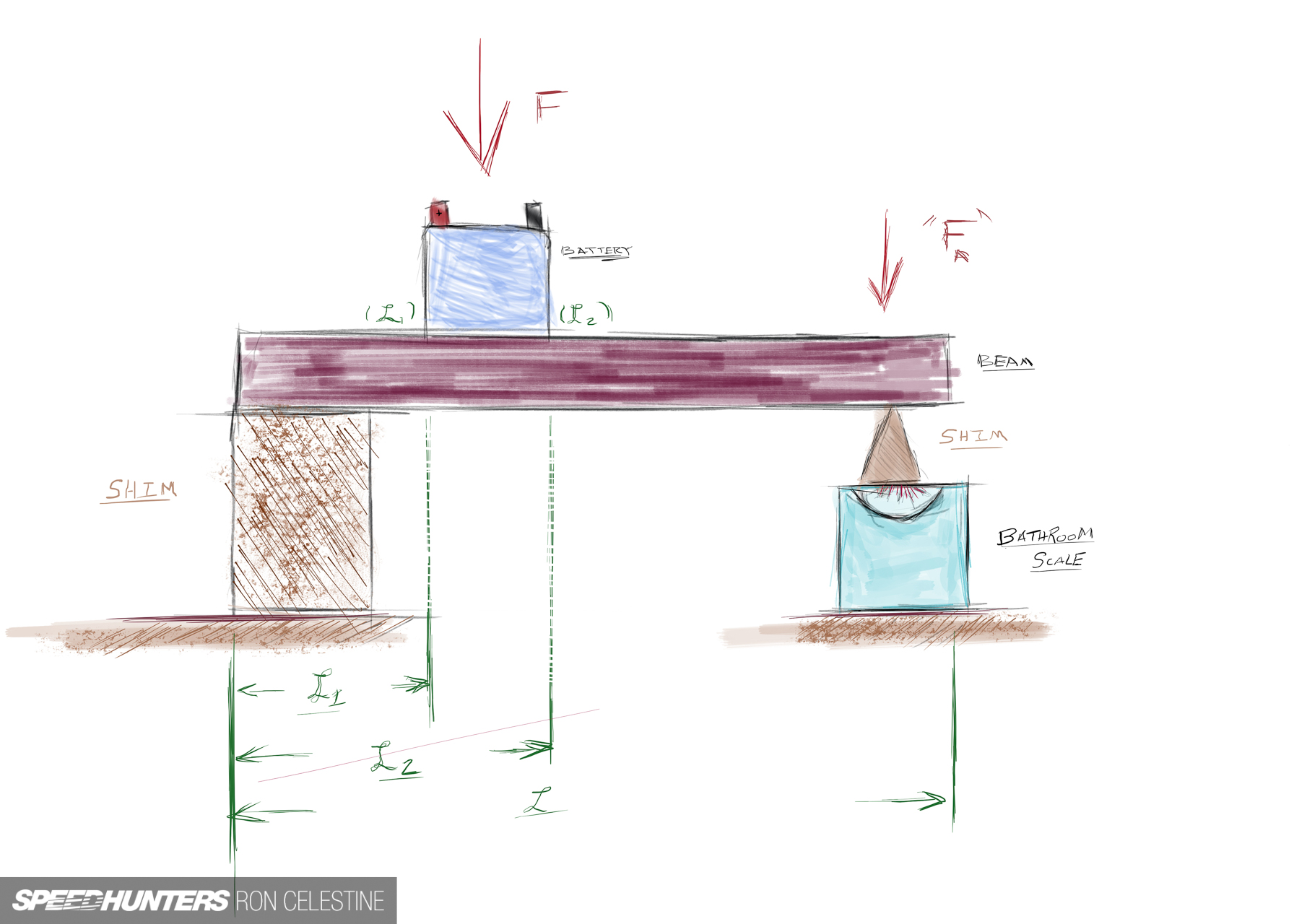
You’ve a supporting block wherein a beam rests on. The supporting block is a ‘X’ distances away from the lavatory scale. You’d then place the tire on the beam, and that weight transfers across the beam to the size. The burden might be significantly smaller, which shouldn’t max out the size. In case you know the gap from the supporting block and the gap to the size, you’ll be able to calculate the actual weight with the worth shown by the size.

Seeing that I still had my analog scales from the primary attempt and a workable platform I designed for aligning cars, I figured I’d let my inner engineer back out to play and provides this a shot. Before going full send, I made a decision to check it on a small scale with an old battery from the family Honda Stepwgn.

I first weighed the battery to know my goal— roughly 9.8kg (21.6lbs). The resolution on these scales leave lots to desire.
I next created a platform that might have the beam level with the lavatory scale. I recorded the length (92.2cm). We are going to call this ‘L’.
Then I placed the battery on the beam and got a reading of two.9kg (6.4lbs). Great! I’ll call that ‘Fa’ for now. Now, to calculate the distances.

Unlike the drawing, the force of the battery isn’t a single point on the beam, thus I made a decision to take the typical of using a distance from in front of and behind the battery – one closest to the size (L2) and one closest to the supporting block (L1). I’d subtract the 2 and divide it by 2.
(L2-L1) /2 = Lm
(39cm-15.5cm) / 2 = Lm
11.75cm = Lm
With what I’m calling ‘Lm’, you’ll be able to subtract that number from L2 and get the battery’s ‘center’ point of force. I’ll call this value ‘Lf’.
L2-Lm= Lf
39cm-11.75cm= Lf
27.25cm= Lf
With Lf now determined, I can divide it by the entire length of the beam. In case you know the gap relative to the beam, you’ll be able to divide that number by the burden on the size to calculate the burden. I comprehend it’s getting a bit wild here…
Fl=Lf /L
Fl=27.25cm / 92.2cm
Fl=.2955
I learned this on the full-size test, but I attempted to maintain as many numbers after the decimal place as possible to extend accuracy. It does make a difference. With Fl, we will finally calculate the burden of F.
F= Fa / Fl
F= 2.9kg. / 2955
F= 9.81kg

That is an error of 0.10%, which greater than proves the accuracy of this mathematical test. With this solid proof of concept, it was time to scale up.
Full Steam Ahead
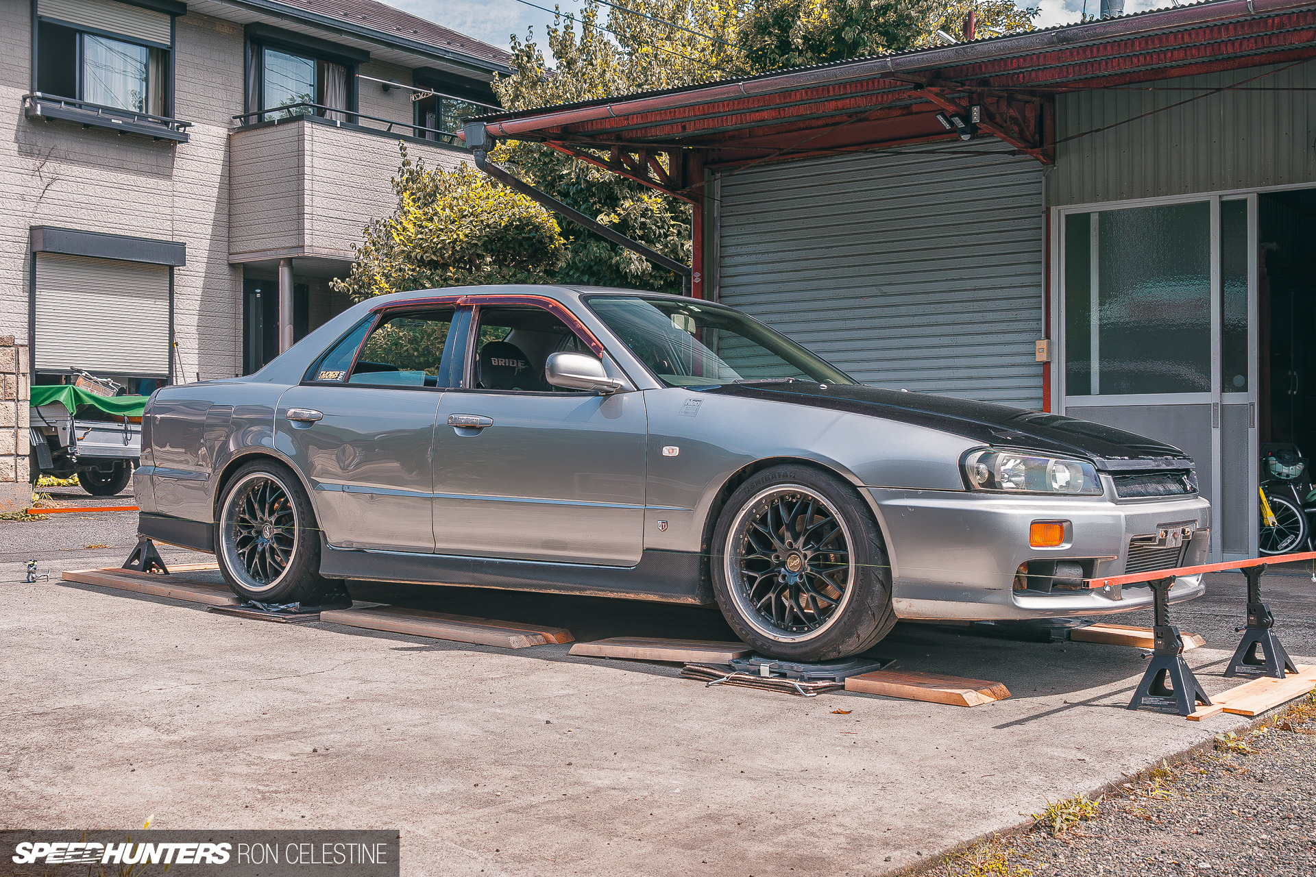
With Project Rough able to go, I made a decision to do an alignment, as I’d use the identical platform rig for the corner balancing.

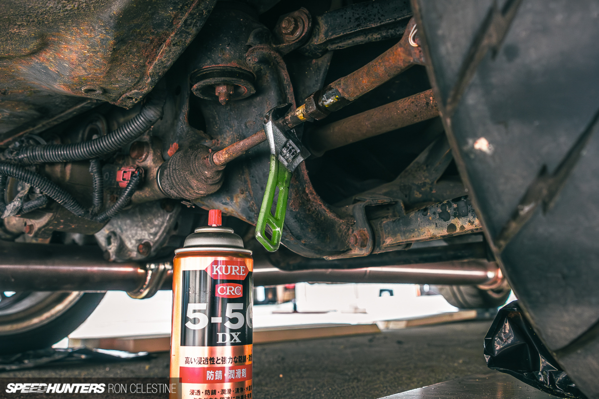
For shaken, I needed to reinstall some OEM parts, which threw my alignment out of whack.

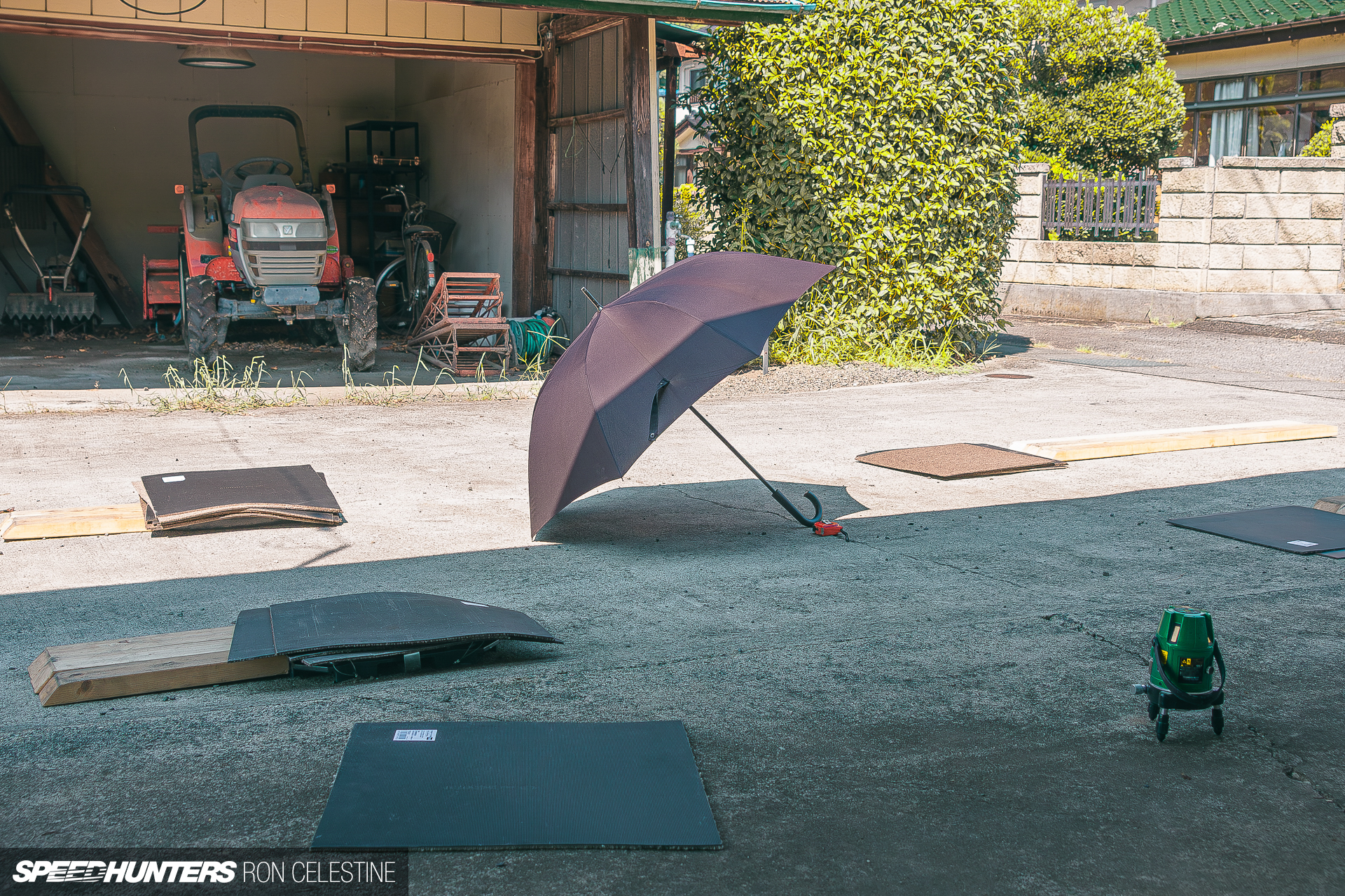
Bringing the automobile to my house from its storage spot was one among the sketchiest drives of my life. I adjusted my laser level to level the platform with shims.

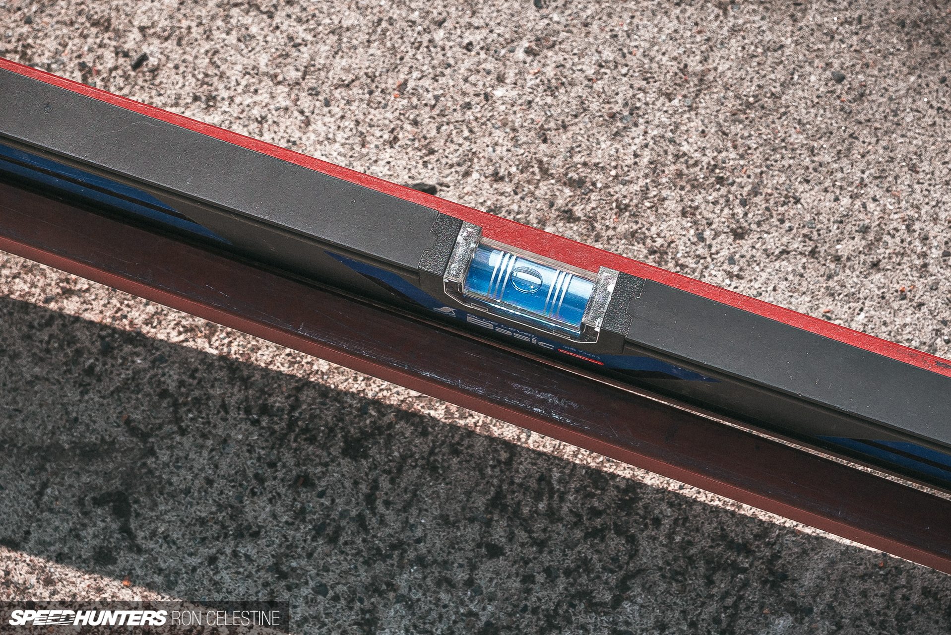
I used to be now able to corner balance Project Rough. I got my bathroom scale out and ensured the beam and platform were level…
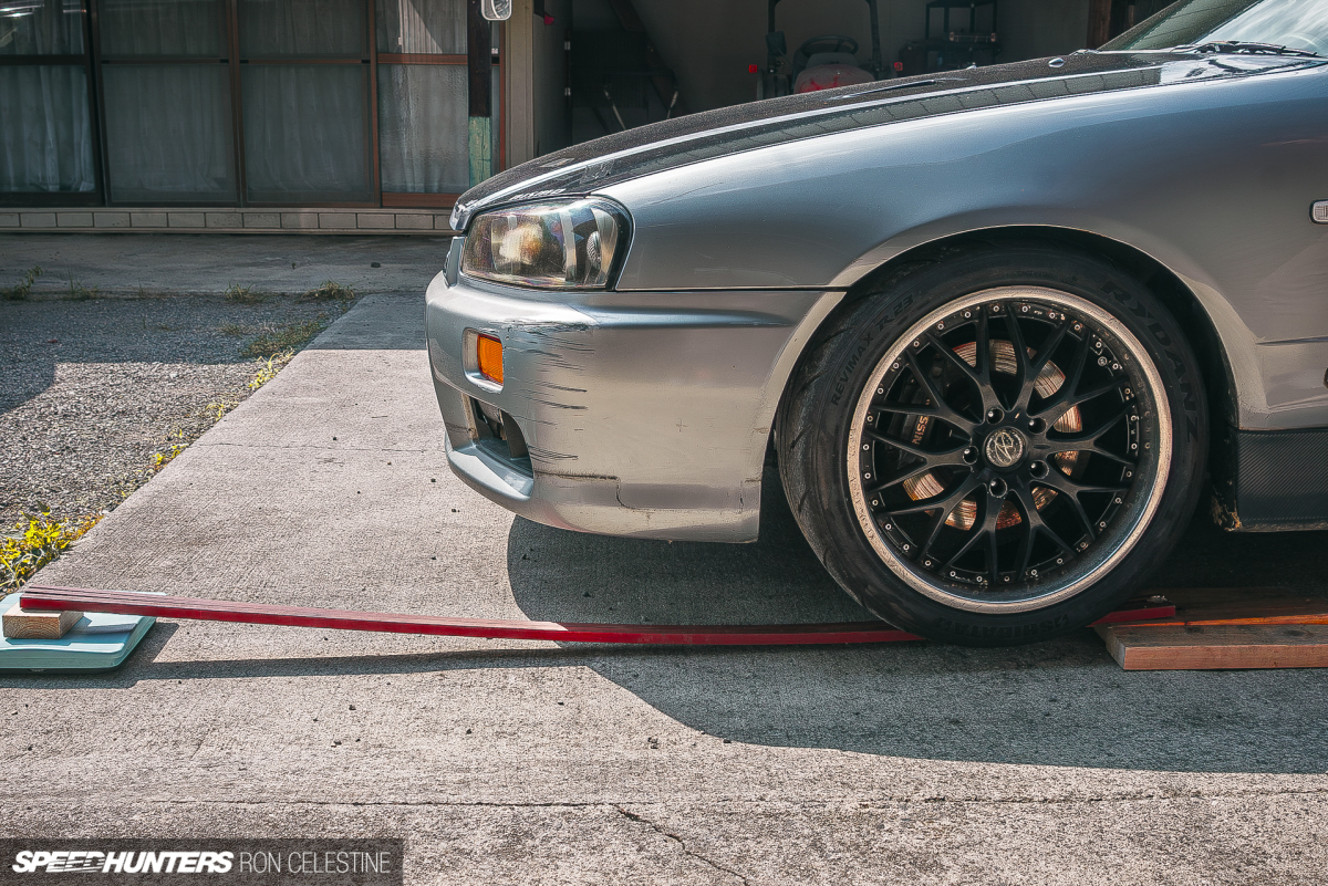

…And immediately bumped into an issue. Although I had calculated that if my bar were 184cm long, I’d have loads of space to drive on the beam and never max out the lavatory scale, the burden deflected the beam a lot that it touched the bottom. Two extrusion bars weren’t going to work.
But how about three? Seeing that I had extra extrusions from various projects at that very same 184cm length, I made a decision to try that before cutting the beams to a smaller size. I used to be still afraid that if I had cut the beams too short and driven too far on the beam, it will max out the size, and I’d risk breaking them.

Even with three beams in place, they still bowed like crazy. This wasn’t going to work. I then remembered that I could move the size closer to the automobile and use a wedge piece of wood for the beams to rest on to transfer the load, effectively shorting the length of the beams. All I needed to do was zero out my scale and check out it.
With my current length (L) now shortened to 108.3cm from 184cm, the beam hardly deflected and will proceed with the experiment. The reading on the size was 42.5kg (93.7lbs) (Fa).

It was now time to calculate the varied lengths as I had done with the battery. Nonetheless, it was harder to inform where the contact patch was on the beam. I used a small square ruler and slid it under the tire until it couldn’t move anymore, after which marked the beam. I did this for each side to get my L2 and L1 calculations.
(L2-L1) / 2 = Lm
(20.5cm-1.1cm) / 2 = Lm
9.7cm = Lm
It wasn’t until I finished measuring all the pieces that I noticed there was a neater approach to determine the tire’s contact patch…


You may press a chunk of flat scrap wood anywhere against the tire and mark out the L2 and L1 of the tire contact patch using the identical method. Amazingly, this method matched my numbers for the front tires (9.7cm) but was barely higher within the rear (10cm). These can be the Lm values utilized in the calculations.

Seeing that I can directly calculate Lm from the tire contact patch, my latest equation is now this.
L2-Lm = Lf
20.5cm -9.7cm = Lf
Lf = 10.8cm
We now take Lf and calculate the force relative to the gap on the beam.
Fl=Lf / L
Fl=10.8cm / 108.3cm
Fl=.0997
Again, keep as many places as possible within the calculations. I stored the whole number on my calculator (0.099722992). Then, we will calculate the force of the automobile at that corner.
F= Fa / Fl
F= 42.5kg.0997
F= 426.18kg
And similar to that, one corner is finished! Next, roll the automobile back a bit, move the size to the following tire, drive up, and crunch those numbers.


When you get the hang of it, each corner takes about five minutes. In fact, if you may have multiple scales and beams (I used to be still cautious and decided to not get more beams to do that), you could possibly do that whole process in a single shot.

Listed here are the values that I got here up with in any case the calculations. Based on the shakensho, my Skyline should weigh 1,460kg (3,218lbs). I’m undecided how they got that number (wet, dry, full tank of gas, etc.), but I shouldn’t be too far off.


Think about an excellent lightweight (read: barely flimsy) FRP front hood, no spare tire, and a number of other bits here and there, and the entire calculated weight is pretty rattling close. Ideally, I’d take Project Rough to a spot where I can drive and weigh the automobile, but that may have to attend until it’s passed its shaken inspection.
What can we do with this newfound details about Project Rough‘s balance? A corner balance shows your vehicle’s weight distribution, which may then be manipulated to optimize handling. For individuals who are dead serious about getting one of the best lap time, you’ll manipulate this distribution by physically removing weight or adding ballast in strategic locations to catch up with to that ‘ideal’ 50/50 distribution front to back and left to right.
We will manipulate how much weight a corner receives by raising or lowering it. Nonetheless, as one motion affects all the opposite corners at the identical time, it isn’t possible to vary the front, rear, left, and right weight percentages. So unless I physically remove, shift, or add weight, Project Rough may have these values.
Front Weight % =54.06%
Rear Weight % =45.95%
Left Weight % =53.23%
Right Weight % =46.77%
Note: I didn’t simulate my body weight (84kg/185lbs) or disconnect the sway bars. In good practice, you absolutely should do that when establishing a race automobile or a automobile with incredibly stiff springs. Minor tweaks may have a much bigger effect, and also you don’t want accidental preload within the sway bars. Although Project Rough has adjustable sway bar end links, and I even have dialed them in for no preload, it isn’t a race automobile. We’re still doing this with bathroom scales no matter what number of variables we limit.
What we can do is get our cross-weight to a really perfect 50/50 situation. Currently:
(Front Right (kg) +Rear Left (kg)) / Total Weight (kg) = Cross Weight %
(351.83kg+340kg) / 1439.27kg =Cross Weight %
48.07% = Cross Weight %
Anytime you may have a cross weight above 50%, you may have a wedge. Anything below 50%, like Project Rough, is a reverse wedge. Knowing this, you’ll be able to follow these rules to regulate the ride height to catch up with to a 50/50 distribution.
RAISING anybody corner will INCREASE the burden on that corner and barely affect all other corners.
LOWERING anybody corner will DECREASE the burden on that corner and barely affect all other corners.
Cross weight ABOVE 50% = DECREASE weight (height) on FR/RL or INCREASE weight (height) on FL/RR. – Wedge
Cross weight BELOW 50% = INCREASE weight (height) on FR/RL or DECREASE weight (height) on FL/RR – Reverse Wedge

Thus, I should work on increasing the peak on the Front Right – Rear Left or decreasing the peak on the Front Left – Rear Right. That is where all the pieces becomes hella-tedious. You furthermore mght need to make a decision how set you’re within the vehicle’s ride height. Again, the stiffer the springs, the stronger the impact minor adjustments will make. Nonetheless, if you happen to are dead set on how the automobile looks, you may should compromise that fifty/50 distribution.
And that’s for you to make a decision. For me, once I get Project Rough back on the road, I’ll do that again and aim to get that fifty/50 cross weight distribution. I also wish to test a number of more suspension projects and experiments.
This goes to point out that if you happen to’re not afraid of a bit of little bit of math, you’ll be able to unlock potential and data that might otherwise be locked behind expensive equipment. It did take some refinement, and this still won’t be as accurate as a great set of electronic scales, but unlike my first attempt at corner balancing with scales, it was a hit.
Electronic scales would still be excellent, though…
Ron Celestine
Instagram: celestinephotography
This Article First Appeared At www.speedhunters.com